Showing posts with label circuit. Show all posts

Friday, January 10, 2014

Simple Dual 50V 5A Universal Power Supply Circuit Diagram

This is the simple Dual 50V/5A Universal Power Supply Circuit Diagram. Tl has two primaries and six secondaries; the two 120-VAC primaries and 6.3-VAC secondaries are in parallel. Modules A and are identical; hence, only Module A`s parts are called out. Module C is wired point-to-point on the IC3 heat-sink.

Dual 50V/5A Universal Power Supply Circuit Diagram

Dual 50V/5A Universal Power Supply Circuit Diagram

Read More..

Thursday, December 26, 2013

V Charger Circuit Diagram

The charger is based on a charging voltage of 2.4 V per cell, in accordance with most manufacturers recommendations. The circuit pulses the battery under charge with 14.4 V (6 cells ? 2.4 V per cell) at a rate of 120 Hz. The design provides current limiting to protect the chargers internal components while limiting the charging rate to prevent damaging severely discharged lead-acid batteries. 

The maximum recommended charging current is normally about one-fourth the ampere-hour rating of the battery. For example, the maximum charging current for an average 44 ampere-hour battery is 11 A. If the impedance of the load requires a charging current greater than the 11 A current limit, the circuit will go into current limiting. The amplitude of the charging pulses is controlled to maintain a maximum peak charging current of 11 A (8 A average).

V Charger Circuit Diagram

V Charger Circuit Diagram

V Charger Circuit Diagram
Read More..

Wednesday, May 29, 2013

FM Jammer Circuit

Here is a Fm jammer circuit diagram.This circuit transmit VHF signals.Normally powerful oscillation of the circuit interrupt FM signals


Note
# Jammers are ban in lots of countries so you shouldnt miss use this and you must assemble this circuit on your own responsibility.
#
For L1 make 6 turns of 16AWG enamelled copper wire on a 9mm plastic former.

Read More..

PWM Power Controller Circuit

This is a circuit that can uses a 555 timer to generate a saw tooth voltage waveform across a capacitor, then compares that signal against a steady voltage provided by a potentiometer, using an op-amp as a comparator. The comparison of these two voltage signals produces a square-wave output from the op-amp, varying in duty cycle according to the potentiometers position. This is the figure of the circuit; 


This variable duty cycle signal then drives the base of a power transistor, switching current and and off through the load. The 555s oscillation frequency is much higher than the lamp filaments ability to thermally cycle (heat and cool), so any variation in duty cycle, or pulse width, has the effect of controlling the total power dissipated by the load over time. Controlling electrical power through a load by means of quickly switching it on and off, and varying the "on" time, is known as pulse-width modulation, or PWM. It is a very efficient means of controlling electrical power because the controlling element (the power transistor) dissipates comparatively little power in switching on and off, especially if compared to the wasted power dissipated of a rheostat in a similar situation. When the transistor is in cutoff, its power dissipation is zero because there is no current through it. When the transistor is saturated, its dissipation is very low because there is little voltage dropped between collector and emitter while it is conducting current.

PWM is a concept easier understood through experimentation than reading. It would be nice to view the capacitor voltage, potentiometer voltage, and op-amp output waveforms all on one (triple-trace) oscilloscope to see how they relate to one another, and to the load power. However, most of us have no access to a triple-trace oscilloscope, much less any oscilloscope at all, so an alternative method is to slow the 555 oscillator down enough that the three voltages may be compared with a simple DC voltmeter. Replace the 0.1 µF capacitor with one that is 100 µF or larger. This will slow the oscillation frequency down by a factor of at least a thousand, enabling you to measure the capacitor voltage slowly rise over time, and the op-amp output transition from "high" to "low" when the capacitor voltage becomes greater than the potentiometer voltage. With such a slow oscillation frequency, the load power will not be proportioned as before. Rather, the lamp will turn on and off at regular intervals. Feel free to experiment with other capacitor or resistor values to speed up the oscillations enough so the lamp never fully turns on or off, but is "throttled" by quick on-and-off pulsing of the transistor.

Read More..

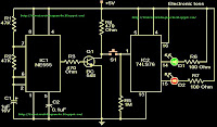
Electronic toss circuit


This is a fun circuit.you can use this one for various games.And there are lots of games tossing is required.so use this for thatNote

#This circuit can be powered With 5v DC
Read More..

Tuesday, May 28, 2013

Brightness controller circuit diagram for your car

This is brightness controller circuit diagram.You can use this circuit for your car or for your bike.Here I have used famous IC NE 555.

Note
# Use 6V bulbs with this
# Build this circuit on a pcb.
Read More..

Tuesday, May 14, 2013

Door alarm circuit Diagram


This is a door alarm circuit.I have used a magnetic-reed switch for this.When the door opens the buzzer will give a beep beep sound.Changing R2 and C2 The period of generating beep sound can be changed.According to the values of this circuit you can get that sound for 4 or 5 seconds.double the value the you can double the time.Note

# this circuit operate with 9V battry.

#Build this circuit on a PCB
Read More..

Infrared motion detector circuit


Here is the circuit diagram of an infrared motion detector that can be used to sense intrusions.Infra red rays reflected from a static object will be in one phase, and the rays reflected from a moving object will be in another phase.The circuit uses this principle to sense the motion.
The IC1 (NE 555) is wired as an astable multivibrator .The IR diode connected at the output of this IC produces infrared beams of frequency 5Khz.These beams are picked by the photo transistor Q1 .At normal condition ie; when there is no intrusion the output pin (7) of IC2 will be low.When there is an intrusion the phase of the reflected waveforms has a difference in phase and this phase difference will be picked by the IC2.Now the pin 7 of the IC 2 goes high to indicate the intrusion.An LED or a buzzer can be connected at the output of the IC to indicate the intrusion.

* Comparators IC2a and IC2b are belonging to the same IC2 (LM1458).So the power supply is shown connected only once.No problem.
* When there is disturbance in the air or vehicles passing nearby,the circuit may get false triggered.
* POT R5 can be used for sensitivity adjustment.

Read More..

Sunday, April 21, 2013

Cheap Bicycle Alarm Schematics Circuit

The author wanted a very cheap and simple alarm for some of his possessions, such as his electrically assisted bicycle. This alarm is based on a cheap window alarm, which has a time-switch added to it with a 1-minute time-out. The output  pulse of the 555 replaces the reed switch in the window alarm. The 555 is triggered by a sensor mounted near the front  wheel, in combination with a magnet that is mounted on the spokes. This sensor and the magnet were taken from a cheap bicycle computer. 

Circuit diagram :
Cheap Bicycle Alarm-Circuit Diagram
Cheap Bicycle Alarm Circuit Diagram

The front wheel of the bicycle is kept unlocked, so that the reed  switch closes momentarily when the wheel turns. This  triggers the 555, which in turn activates the window alarm. The circuit around the 555 takes very little current and can  be powered by the batteries in the window alarm.  There  is just enough room  left inside the enclosure of the window  alarm to mount the time-switch inside it. 

The result is a very cheap, compact device, with only a single cable going to the reed switch on the front wheel. And the noise this thing produces is just unbelievable! After about one minute the noise stops and the alarm goes back into standby mode. The bicycle alarm should be mounted in an inconspicuous place, such as underneath the saddle, inside a (large) front light, in the battery compartment, etc.
Hopefully the alarm scares any potential thief away, or at least it makes other members of the public aware that something isnt quite right. 

Caution. The installation and use of this circuit may be subject to legal restrictions in your country, state or area.


Read More..

Saturday, April 13, 2013

Class AB Power Amplifier Circuit 30w Using Power Transistor


30W Class AB power amplifier circuit diagram using power transistor. Set the above amplifier up by adjust the variable resistor R1 to maximum and R12 to zero. After this set up is done, the activate / turn on the amplifier. Adjust the R1 so that the measured output offset is between 30 and 100mV. Once set, adjust the R12 slowly to achieve a quiescent current of around 120mA. Keep checking the quiescent current as the amplifier heats up as it might change due to voltage drop changes in the output devices because of the heat. The heatsinks should be 0.6K/W or less for two amplifiers.

Power supply circuit for 30W class AB power amplifier:
power supply for 30W Class AB Power Amplifier Circuit
30W Class AB Power Amplifier Circuit, Link
Read More..

AVR Dongle Circuit

This circuit is intended to program AVR controllers one of theses the AT90S1200 by manner of the parallel port. The circuit is extremely simple. IC1 gives buffering for the indicators that shuttle from the parallel port to the microcontroller and vice versa. This is essentially the entire thing that could be mentioned concerning the circuit. The two boxheaders (K2 and K3) have the ‘standard’ ISP (in gadget applicationming) pinout for the AVR controllers. The manufacturer suggests these two pinouts in an try to create a kind of standard for the in-circuit applicationming of AVR-controllers. These connections may also be found on many development boards for these controllers. The instrument carries out the true programming task.

Circuit diagram :
\"AVR_Dongle_Circuit_Diagramw\"
AVR Dongle Circuit Diagram

It is subsequently essential to have a application (ATMEL AVR ISP), which is on hand as a free obtain from http://www.atmel.com. The development of the circuit must made on standard prototype board, on the grounds that we didn’t design a PCB for this circuit. This shouldn't present any difficulties taking into account the small selection of sections involved. We suggest that inexperienced builders first make a copy of the circuit and pass off every connection on the schematic as soon as it has been made on the board. This makes it simple to check in a whiles whether all connections had been made or no longer.

http://www.ecircuitslab.com
Read More..

Friday, April 12, 2013

12 VOLT AUDIO AMPLIFIER IC TDA7222AP CIRCUIT DIAGRAM

12 VOLT AUDIO AMPLIFIER IC TDA7222AP CIRCUIT DIAGRAM


Note


Use 12V DC for powering the circuit.

The IC must be heatsinked.

Speaker can be a 4 ohms one.

For optimum performance input and output must be separately grounded.


Pin Name Description

1 Vcc Supply Voltage

2 RR Ripple Reject

3 MC Muting control

4 OP AF Signal Input

5 FB FB Filter

6 GA Gain adjust

7 GND Ground

8 GND Ground

9 OP AF Output

10 BS BootStrap

Read More..

Thursday, April 11, 2013

Park Aid Circuit

Three LEDs signal bumper-barrier distance, Infra-red operation, indoor use
This circuit was designed as an aid in parking the car near the garage wall when backing up. LED D7 illuminates when bumper-wall distance is about 20 cm., D7+D6 illuminate at about 10 cm. and D7+D6+D5 at about 6 cm. In this manner you are alerted when approaching too close to the wall. All distances mentioned before can vary, depending on infra-red transmitting and receiving LEDs used and are mostly affected by the color of the reflecting surface. Black surfaces lower greatly the device sensitivity. Obviously, you can use this circuit in other applications like liquids level detection, proximity devices etc.
Circuit operation:
IC1 forms an oscillator driving the infra-red LED by means of 0.8mSec. pulses at 120Hz frequency and about 300mA peak current. D1 & D2 are placed facing the car on the same line, a couple of centimeters apart, on a short breadboard strip fastened to the wall. D2 picks-up the infra-red beam generated by D1 and reflected by the surface placed in front of it. The signal is amplified by IC2A and peak detected by D4 & C4. Diode D3, with R5 & R6, compensates for the forward diode drop of D4. A DC voltage proportional to the distance of the reflecting object and D1 & D2 feeds the inverting inputs of three voltage comparators. These comparators switch on and off the LEDs, referring to voltages at their non-inverting inputs set by the voltage divider resistor chain R7-R10.
Circuit diagram:
Park-Aid Circuit Diagram
Parts:
R1_____________10K 1/4W Resistor
R2,R5,R6,R9_____1K 1/4W Resistors
R3_____________33R 1/4W Resistor
R4,R11__________1M 1/4W Resistors
R7______________4K7 1/4W Resistor
R8______________1K5 1/4W Resistor
R10,R12-R14_____1K 1/4W Resistors
C1,C4___________1µF 63V Electrolytic or Polyester Capacitors
C2_____________47pF 63V Ceramic Capacitor
C3,C5_________100µF 25V Electrolytic Capacitors
D1_____________Infra-red LED
D2_____________Infra-red Photo Diode (see Notes)
D3,D4________1N4148 75V 150mA Diodes
D5-7___________LEDs (Any color and size)
IC1_____________555 Timer IC
IC2___________LM324 Low Power Quad Op-amp
IC3____________7812 12V 1A Positive voltage regulator IC
Circuit modification:
A circuit modification featuring an audible alert instead of the visual one is available here: Park-Aid Modification
Notes:
  • Power supply must be regulated (hence the use of IC3) for precise reference voltages. The circuit can be fed by a commercial wall plug-in adapter, having a DC output voltage in the range 12-24V.
  • Current drawing: LEDs off 40mA; all LEDs on 60mA @ 12V DC supply.
  • The infra-red Photo Diode D2, should be of the type incorporating an optical sunlight filter: these components appear in black plastic cases. Some of them resemble TO92 transistors: in this case, please note that the sensitive surface is the curved, not the flat one.
  • Avoid sun or artificial light hitting directly D1 & D2.
  • If your car has black bumpers, you can line-up the infra-red diodes with the (mostly white) license or number plate.
  • It is wiser to place all the circuitry near the infra-red LEDs in a small box. The 3 signaling LEDs can be placed far from the main box at an height making them well visible by the car driver.
  • The best setup is obtained bringing D2 nearer to D1 (without a reflecting object) until D5 illuminates; then moving it a bit until D5 is clearly off. Usually D1-D2 optimum distance lies in the range 1.5-3 cm.
  • If you are needing a simpler circuit of this kind driving a LED or a relay, click Infra-red Level Detector
Source : www.redcircuits.com
Read More..

Remote controlled appliance switch circuit


Here is a versatile remote controlled appliance switch that can ON or OFF any appliance connected to it using a TV remote.


IR remote sensor IC TSOP 1738 is used for receiving the signal. Normally when no signal is falling on IC3 the output of it will be high.This makes Q1 OFF.When a signal of 38 KHz from the TV remote falls on the IC3 its output goes low.This makes Q1 conduct and a negative pulse is obtained at pin 2 of IC 1 NE 555.Due to this IC1 wired as a monostable multivibrator produces a 4 Sec long high signal at its out put.This high out put is the clock for IC 2 which is wired as a Flipflop and of , its two outputs pin 3
goes low and pin 2 goes high.The high output at pin 2 is amplified to drive the relay .For the next signal the outputs of IC2 toggles state. Result, we get a relay toggling on each press on the remote.Any appliance connected to this circuit can be switched ON or OFF.


Notes .

* Before wiring the circuit make sure that the carrier frequency of the
TV remote you have is 38 kHz.For that wire the sensor part only ,point your
remote to the TSOP1738 and press any switch.If out put of TSOP1738 goes
low then OK, your remote is of 38Khz type.Nothing to worry almost all TV
remote are of this type.

* You can use any switch of the remote because for any switch the code only changes,
the carrier frequency remains same.We need this carrier frequency only.

* Assemble the circuit on a good quality PCB or common board.

* The appliance can be connected through NO or NC and C contacts of the relay .

* Use a regulated 6V power supply for the circuit.
Read More..

LM4017 TC4011 10 LED roulette circuit with explantion


When
entering the power supply circuit, and switch S1 (Start), which is
attached press release switch off.Then current is flowing through R1,
R2, and C2.
Makes the capacitor C2 caused up When the switch S1
allows the C2 to discharge through R3. The pressure this causes the
clock input to the pin 8 of IC1a. The IC1a which will work with
production IC1b frequency to send it to the leg 14 (Clock) Of IC2.The
IC2 is a driver by ICs LED 10 is illuminated by the moon to the incoming
frequency. The IC1d the IC1c and work together. It will serve up audio
frequency generator, and then sent to the Piano Society (PZ1) loud
beep came out with LED light period.
source:eleccircuit.com
Read More..

IR Remote Control Home Appliance Circuit Diagram


This
is the most popular IR Remote control circuit for home appliances like
lamp, fan, radio, tv etc to make the appliance turn on/off from a TV,
VCD or DVD remote control. It is very simple to build because of few
components and simple design.
The
circuit can activated from up to 10 metres. The 38kHz infrared (IR)
rays generated by the remote control are received by IR receiver module
TSOP1738 of the circuit. Pin 1 of TSOP1738 is connected to ground, pin 2
is connected to the power supply through resistor R5 and the output is
taken from pin 3. The output signal is amplified by transistor T1
(BC558).

The amplified signal is fed to clock pin 14 of decade
counter IC CD4017 (IC1). Pin 8 of IC1 is grounded, pin 16 is connected
to Vcc and pin 3 is connected to LED1 (red), which glows to indicate
that the appliance is ‘off.’ The output of IC1 is taken from its pin 2.
LED2 (green) connected to pin 2 is used to indicate the ‘on’ state of
the appliance. Transistor T2 (BC548) connected to pin 2 of IC1 drives
relay RL1. Diode IN 4148 acts as a freewheeling diode. The appliance to
be controlled is connected between the pole of the relay and neutral
terminal of mains. It gets connected to live terminal of AC mains via
normally opened (N/O) contact when the relay energises. you can use any
NPN transistor inplace of BC548. You can also use SL100 or any NPN
transistor lying around you.
The
delay depends on the C1 capacitor. Using higher value capacitor will
create more delay and using less value capacitor will switch the circuit
more than 2 times when you press a remote. Analyse the circuit by
placing the 10uf capacitor in place of C1 (100uf).
Read More..

Wednesday, April 10, 2013

Car Battery Saver Circuit

Prevents the complete discharge of the battery when the door is left open accidentally

I recently forgot to close the door of my car after parking in the garage and I found the battery completely exhausted after the week-end, when I tried to start the engine on Monday morning. This inconvenience prompted me to design a simple circuit, capable of switching-off automatically after a few minutes the inside courtesy lamp, the real culprit for the damage.

Circuit operation:

When the door is opened, SW1 closes, the circuit is powered and the lamp is on. C1 starts charging slowly through R1 and when a voltage of 2/3 the supply is reached at pins #2 and #6 of IC1, the internal comparator changes the state of the flip-flop, the voltage at pin #3 falls to zero and the lamp will switch-off. The lamp will remain in the off state as the door is closed and will illuminate only when the door will be opened again. The final result is a three-terminal device in which two terminals are used to connect the circuit in series to the lamp and the existing door-switch. The third terminal is connected to the 12V positive supply.

Circuit diagram :

Car Battery Saver Circuit Diagram

Car Battery Saver Circuit Diagram

Notes:

  • With the values specified for R1 and C1, the lamp will stay on for about 9 minutes and 30 seconds.
  • The time delay can be changed by varying R1 and/or C1 values.
  • The circuit can be bypassed by the usually existing switch that allows the interior lamp to illuminate continuously, even when the door is closed: this connection is shown in dotted lines.
  • Current drawing when the circuit is off: 150µA.
Read More..

5 Band Graphic Equaliser circuit with LA3600 and PCB

General Description
Graphic equalisers are a must in any good hi-fi systems! They enable you to shape the response of the system to the particular room, or in recordings to improve deficiencies of the equipment or the original recording. A good equalizer, used with skill can dramatically improve the quality of your listening pleasure.
This equalizer has five bands which cover all the audible frequencies, centred at 100, 320, 1,000, 3,500 and 10,000 Hz. The spacing between peak frequencies is two octaves which is quite adequate for most domestic applications. Frequency adjustment is 12dB/octave.
 
The circuit is for one channel and if you want to use it for STEREO you should build two, one for each channel of your system.
Technical Specifications – Characteristics
Working voltage: 6-15V DC
Frequency response: 20Hz-20KHz
Current: 60 ma
How it Works
This equaliser has five bands which cover all the audio frequencies, around 100, 320, 1,000, 3,500 and 10,000 Hz.
The circuit is for one channel and if you want to use it for STEREO you need two. The circuit consists of one LA3600 IC.
The circuit has been designed so that when the potentiometers are in the middle of their travel the signal is not affected at all. Turning a potentiometer in either direction will affect the corresponding frequency range accordingly. The maximum output voltage without distortion is 1 Vpp. The equaliser operates from a 12 VDC power supply which makes it suitable for use in home or car.
Construction
This work is not very difficult and if you stick to a few rules you should have no problems. The soldering iron that you use must be light and its power should not exceed the 25 Watts. The tip should be fine and must be kept clean at all times. For this purpose come very handy specially made sponges that are kept wet and from time to time you can wipe the hot tip on them to remove all the residues that tend to accumulate on it. The construction of the equaliser is very easy if you follow the diagrams and our advice carefully. The only really sensitive component are the IC. Start building the circuit by soldering the pins and the IC sockets in their places on the p.c. board. Solder then the resistors, the capacitors, making sure that the electrolytic are inserted the right way round before soldering them, and finally the potentiometers.
 
 Depending on the size and the shape of the case you are going to use for the project you can either solder the potentiometers on the p.c. board directly or use short pieces of shielded audio cable to connect them with the rest of the circuit. When you have finished soldering the components on the board check everything for possible mistakes, clean the board with a solvent to remove all traces of soldering flux and insert the IC’s in their sockets. Make sure that you align them properly and that you do not bend their pins during insertion. Make then the following connections using shielded cable for the input and output and preferably twisted twin cable for the power supply.
- The supply (6-15 VDC recommend 12volt DC) must be connected at points 1 (+) and 2 (-) of the board.
- The input is at points 5 (signal) and 4 (earth).
- The output is at points 3 (signal) and 4 (earth).
If you turn the power on, and the potentiometers of the equaliser are in their middle position there shouldn’t be any notice able difference to the music if the equaliser is inserted or not in the signal path. However turning the potentiometers should produce a noticeable effect to the reproduction.


Parts
C1 = 2.2mF 22v
C2 = 47nF
C3 = 680nF
C4 = 15nF
C5 = 220nF
C6 = 4.7nF
C7 = 68nF
C8 = 1.2nF
C9 = 22nF
C10 = 470pF
C11 = 6.8nF
C12 = 1nF
C13 = 2.2mF
C14 = 100mF 22v
C15 = 100mF 22v
R1 = 4.7k
R2 = 10k
R3, 4, 5, 6, 7 = 100k Potentiometers
IC = LA3600 link
 
Read More..

Monday, April 8, 2013

Circuit Detector and Disconnecting Over Voltage Schematic

The circuit in this figure is protecting the circuit and the system with power supplies that may exceed safe limits. One example is small consumer products that use external ac adapters; its easy to mistakenly plug in the wrong adapter. Another example is a portable system that uses a rechargeable battery pack. If the battery pack is absent or fails to open during recharging, a high-compliance charger can deliver excessive voltages to the system.


The circuit works using LM4041 adjustable shunt-voltage regulator as a voltage detector. When it operates as a reference, the LM4041 develops a voltage across its positive and negative terminals. This signal forces the voltage across R1 to equal 1.24V. In this circuit, however, R3 prevents this servo action. With R3 in the circuit, VG is near ground when the voltage across R1 is less than 1.24V, and VG is approximately 1V below the positive rail when the voltage across R1 is greater than 1.24V. You can, therefore, set a threshold voltage by selecting appropriate values of R1 and R2. When the supply voltage exceeds the threshold, VG goes high, thereby turning off Q1 and removing power from the load. Select R1 and R2 according to:

It where VSHUTOFF is the supply voltage that causes shutoff. With the values shown, the circuit removes power from the load when the supply voltage reaches approximately 6V. R4 provides hysteresis to prevent chattering when the supply voltage is near the shutoff value. IC1 can accommodate shutoff voltages as high as 10V; clamping IC1s supply voltage with another inexpensive shunt reference or zener diode (across the positive and negative terminals) allows higher maximum shutoff voltages. Maximum supply voltage with the components is approximately 50V.

Read More..

LED Flasher Circuit Using 555 Timer IC

This is a simple LED flasher project that uses a common 555 timer IC for its operation. It is configured as an astable mode which means that its output is a square wave oscillator. Two LEDs are connected to its output in such a way that when one LED is ON, the other LED will turn OFF. 

It uses only 10 simple parts that are easily available at any electronic shops. Capacitor C2 charges exponentially through resistors R1, R2 and the resistance of the trimpot. When C2 has charged to about 2/3 VCC it stops charging and it discharges to about 1/3 VCC through R2 and the trimpot resistance via pin 7. This is the standard operation of a 555 timer. When a Vcc of 5 V to 15 V DC is applied to the circuit, the LED will start to flash.
The frequency of the flashing can be changed by varying the resistance of the potentiometer or trimpot.Parts List The parts list of the simple LED project is as shown below.

Read More..