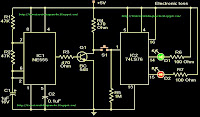
An electronic incubator thermostat circuit shown in this article is not only simple to build but is also easy to set and acquire exact tripping points at various different set temperature levels. The setting may be completed through two discrete variable resistors. The sensing range is quite good from 0 to 110 degrees Celsius.
Switching a particular load at different threshold temperature levels doesn’t necessarily need complex configurations to be involved in an electronic circuit. Here we discuss a simple construction procedure of an electronic incubator thermostat.
This simple electronic incubator thermostat will very faithfully sense and activate the output relay at different set temperature levels from 0 to 110 degree Celsius.
The conventional electromechanical temperature sensors or thermostats are not very efficient due to the simple reason that they cannot be optimized with accurate trip points.
Normally these types of temperature sensor or thermostats fundamentally use the ubiquitous bimetal strip for the actual tripping operations. When the temperature to be sensed reaches the threshold point of this metal, it bends and buckles.
Since the electricity to the heating device passes through this metal, it’s buckling causes the contact to break and thus power to the heating element is interrupted - the heater is switched off and the temperature starts falling. As the temperature cools, the bimetal starts straightening to its original form. The moment it reaches its previous shape, the electricity supply to the heater is restored through its contacts and the cycle repeats.
However, the transition points between the switching are too long and not consistent and therefore not reliable for accurate operations.
The circuit presented here is absolutely free from these drawbacks and will produce comparatively high degree of accuracy as far the upper and the lower tripping operations are concerned.
Parts List
R1 = 2k7,
R2, R5, R6 = 1K
R3, R4 = 10K,
D1---D4 = 1N4007,
D5, D6 = 1N4148,
P1 = 10K,
VR1 = 200 Ohms, 1Watt,
C1 = 1000uF/25V,
T1 = BC547,
T2 = BC557,
IC = 741,
OPTO = LED/LDR Combo.
Relay = 12 V, 400 Ohm, SPDT.
Circuit Description
We know that every semiconductor electronic component changes its electrical conductivity in response to the varying ambient temperature. This property is exploited here to make the circuit work as a temperature sensor and controller.
Diode D5 and transistor T1 together form a differential temperature sensor and interact greatly with each other with changes in the respective surrounding temperature.
Also since D5 acts as the reference source by staying at the ambient temperature level should be kept as far as possible from T1 and in open air.
Pot VR1 may be used externally to optimize the reference level set naturally by D5.
Now assuming D5 is at a relatively fixed temperature level (ambient), if the temperature in question around T1 starts rising, after a particular threshold level as set by VR1, T1 will begin to saturate and gradually start conducting.
Once it reaches the forward voltage drop of the LED inside the opto-coupler, it will start glowing correspondingly brighter as the above temperature rises.
Interestingly as the LED light reaches a particular level, further set by P1, IC1 picks this up and instantly switches its output.
T2 along with relay also respond to the IC’s command and respectively actuate to trip off the load or the heat source in question.
How to go About with the Opto-Coupler?
It’s very simple. Cut a piece of general purpose board about 1 by 1 inch.
Bend the LDR leads near its “head.” Also take a green RED LED, bend it just as the LDR (See figure and Click to Enlarge).
Insert them over the PCB so that the LED lens point is touching the LDR sensing surface and are face to face.
Solder their leads at the track side of the PCB; do not cut off the remaining excess lead portion.
Cover the top with an opaque lid and make sure its light proof. Preferably seal off the edges with some opaque sealing glue.
Let it dry. Your home made opto-coupler is ready and may be fixed over the main circuit board with its leads orientations done as per the electronic incubator thermostat circuit schematic.