Many occasions the hobbyist desires to have a simple, twin power provide for a undertaking. Existing power provides could also be massive both in energy output or bodily measurement. a easy Dual Power Supply is essential.For most non-critical softwares the very very best & simplest choice for a voltage regulator is the 3-terminal sort.The three terminals are enter, ground & output.
The 78xx & 79xx sequence can present as much as 1A load current & it have on chip circuitry to prevent damage in the experience of over warmthing or excessive current. That is, the chip principally shuts down than blowing out. These regulators are cheap, easy to make use of, & they make it sensible to design a technique with lots of P C Bs during which an unregulated provide is brought in & regulation is finished in the neighborhood on each and every circuit board.
This Dual Power Supply challenge gives a twin power supply. With the appropriate choice of transformer & 3-terminal voltage regulator pairs that you can be ready to basically construct a tiny energy provide delivering as so much as amp at +/- 5V, +/- 9V, +/- 12V, +/-15V or +/-18V. You require to supply the center tapped transformer and the 3-terminal pair of regulators you require:7805 & 7905, 7809 & 7909, 7812 & 7912, 7815 & 7915or 7818 & 7918.
The person should pick the pair they wants for hellos phaseicular application.
Note that the + & - regulators don't have to be matched: which you might for instance, use a +5v & -9V pair. However,the optimistic regulator should be a 78xx regulator, & the terrible a 79xx. They have in-built plenty of safety in to this venture so it ought to present loads of years of constant carrier.
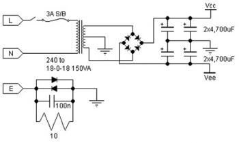
Transformer
This Dual Power Supply design makes use of a full wave bridge rectifier coupled with a centre-tapped transformer. A transformer with a power output rated at as a minimum 7VA ought to be used. The 7VA score means that the most present which may also be delivered without overheating might be around 390mA for the 9V+9V tap; 290mA for the 12V+12V and 230mA for the 15V+15V. If the transformer is rated via output RMS-current then the price should be divided by way of one.2 to get the current which can be provided. For instance, in this case a 1A RMS can deliver 1/(one.2) or 830mA.
Rectifier
They use an epoxy-packaged four amp bridge rectifier with at the least a top reverse voltage of 200V. (Note the phase numbers of bridge rectifiers should no longer standardised so the number are completely different from totally different manufacturers.) For security the diode voltage ranking should be at the least to instances that of the transformers secondary voltage. The present rating of the diodes needs to be two occasions the maximum load present in an effort to be drawn.
Filter Capacitor
The goal of the filter capacitor is to easy out the ripple in the rectified AC voltage. Theres dual quantity of ripple relies on the price of the filer capacitor: the massiver the worth the smaller the ripple.The two,200uF is a suitable value for all the voltages generated the use of this undertaking. The other consideration in choosing the proper capacitor is its voltage ranking. The working voltage of the capacitor needs to be better than the height output voltage of the rectifier. For an 18V supply the height output voltage is one.4 x 18V, or 25V. So they have got chosen a 35V rated capacitor.
Regulators
The unregulated input voltage should all the time be greater than the regulators output voltage via at least 3V to be sure that it to work. If the enter/output voltage difference is bigger than 3V then the surplus doable have to be dissipated as heat. Without a heat sink three terminal regulators can dissipate about two watts. A easy calculation of the voltage totally differential occasions the current drawn will provide the watts to be dissipated. Over two watts a heat sink need to be presentd. If now not then the regulator will automatically flip off if the inner temperature reaches 150oC. For security it is always perfect to utilize a small heat sink even in case you don't suppose you are going to want.
Stability
C4 & C5 improve the regulators potential to react to unexpected adjustments in load current & to forestall uncontrolled oscillations.
Decoupling
The mono block capacitor C2 & C6 throughout the output offers high frequency decoupling which preserve the impedance low at high frequencies.
LED
Two LEDs are provided to point out when the output regulated power is on-line. You don't should make use of the LEDs in the adventure you don't require to. However, the LED on the negative side of the circuit does present a most load to the 79xx regulator which they found essential within the coursework of testing. The bad 3-pin regulators didn't like a nil load situation. They have presentd a 470R/0.5W resistors as the present limiting resistors for the LEDs.
Diode Protection
These give safety to notably against any again emf which can come again in to the facility provide when it provides energy to inductive tons. They additionally present additional short circuit offer protection toion in the case that the positive output is connected accidentally to the negative output. If this happened the standard current limiting shutdown in each and every regulator won't work as meant. The diodes will brief circuit on this case & offer protection to the two regulators.

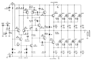
 2 Watt Audio Power Amplifier with Selectable Shutdown Logic Level